

If you are working on a big project it's extremely important that you care about good performance. It's a widespread belief that the graphics that can be made depend only on the 3D engine that's being used. Of course a better engine can lead to better results. But the more potential an engine has, the more difficult it is to use all the features that are required to make the game run fluently. The complexity of the game that can be made with an engine depends only on how many possibilities are offered to optimize performance of the game. Usually the easiest way to realize something is not the most efficient one. It needs some experience and knowledge to find the optimal solution. You also need an understanding of how Ultimate 3D works internally. This tutorial will help you to learn these things.
For advanced programmers the following general hints should be quite self-evident. But since it is extremely important to know about them they will be listed here again. One of the most important things you have to know is that the vertex count and the triangle count are extremely important factors for the performance of your game. Calculating all the data that is required for a vertex takes some computing time so you should use as few vertices as possible when making a new model for your game. If you are working in a professional modeling program such as Blender or 3D Studio Max you can use plugins to optimize your meshes (in Blender it is the Decimate modifier). Less complex modeling programs will at least have a feature that allows you to see how many vertices the model is made up of currently. This is useful for reducing the vertex count manually. Of course, the easiest way to get models with a low vertex count is not to waste vertices from the start of modeling. Be extremely careful with features that subdivide the faces of the models to make them look smoother. Also, do not use high subdivision counts when creating primitive objects (the variables partsx, partsy and partsz).
The next hint is less self-evident. The performance of your game also depends on how many pieces of geometry have to be rendered separately. If you have two pieces of geometry in your model, Ultimate 3D will only render them together if they are using the same material and are part of the same mesh. So the absolute worst case would be a model in which you have forty different meshes, each made up of no more than 20 triangles but still using three different materials. In this case Ultimate 3D would not be able to draw more than 10 triangles simultaneously. So be economical with the number of different materials and use meshes that are made up of a lot of geometry when modeling. Often the use of one textured material is more efficient than the use of three or four different materials and usually it even looks better this way.
You should not use too big textures since they take a lot of memory. The more memory your textures eat up the earlier the video memory of the graphics device will be full. Then system memory will need to be used and in this case the texture needs to be passed from the system memory to the video memory in every step, which is very time intensive. So if you have lots of textures loaded simultaneously you should release as many as possible by calling ReleaseTexture(...). Apart from that, you really should use dimensions that are made up of powers of two for all your textures. If you load a texture with a size of 512*512 it will be loaded with exactly this size, but if you load a texture with a size of 513*513 it will be scaled up to the next higher powers of two which are 1024*1024. It's quite obvious that this is a giant waste of memory and computing time.
Be economical with the number of light sources in your scene. If you have an extremely high number of light sources it will take a lot of computing time for every single vertex. In this case it may be more efficient to learn how to use Deled or other modeling software to realize light mapping. To get an efficient game you have to find a compromise between flexible and static solutions very often. Flexibility always requires a lot of computing time but is usually less work and makes the game seem more lively. Static solutions take more memory since you have some precomputed data, but will take much less computing time and may look much better since it does not matter how much time it took to precompute the static data. The comparison between per vertex or per pixel lighting and light mapping is a great example of this. A repetition of how expensive shadow casting is in terms of computing time hopefully is not needed here.
Ultimate 3D offers a couple of different possibilities to handle a piece of geometry loaded from a model file. You can create LoDs for it or you can handle it as a primitive object. Either of these possibilities could be the best one, depending on the situation. Sometimes it may be more efficient to draw a model with LoDs; sometimes the opposite may be the case. There are also cases in which it's much more efficient to handle geometry as a primitive object; in other cases it makes no sense at all. This subchapter contains some information about the correct use of the different ways to handle models and gives information on which is best in different scenarios.
Let's begin with the proper use of different levels of detail. It's a really practical feature that Ultimate 3D can do automatically and often it can greatly increase the performance of your game. In general, it should be used for any model that has to look very detailed when it's close to the camera. But as I already said you should never use it for models that use frame animation (either models loaded from *.md2 files or animations created using AddFrame(...) ). It also makes no sense to use LoDs if you can not get far enough away from the model anyway. For example, if you have some first person game in which you are always only in small rooms, the use of LoDs would be inefficient. In this case there's a much better way to optimize the game. It will be introduced below.
There are some cases in which it can lead to a giant improvement in performance when you use the function CreatePrimitiveFromModel() and other cases in which it would be extremely inefficient. In general, primitives are perfect for all kinds of simple, static objects the level is made up of. For example, if you have simple wall models that do not need any effects to look good and are made up of less than 100 vertices, it would be the perfect opportunity to use a primitive. Primitives are also perfect for rendering vegetation. So you really should use it if it's possible. Of course it's a bit difficult to make a complex model with only one texture but the result is worth the work. I recommend using *.an8 files for models you want to use with this function, because for those Ultimate 3D will put everything together to one mesh automatically.
In contrast to earlier versions of Ultimate 3D Ultimate 3D 2.0 beta 3 and newer has no problems with partially transparent textures. In earlier versions those lead to display failures very often. Unfortunately the price for this is quite high. The whole object needs to be rendered twice in case it uses a partially transparent texture. The first pass renders only the parts with full opacity, the second pass renders only the parts with full transparency. Since this can reduce the performance strongly, Ultimate 3D allows you to disable this method for particular objects. Then partially transparent stuff will become fully transparent, but it will speed things up a lot.
This function turns alpha blending on or off for the given model object or primitive object. By default alpha blending is turned on.
SwitchAlphaBlending(
EnableDisable
) |
|---|
EnableDisable
If you pass true for this parameter, partially transparent parts will be rendered in a second pass (performance costly), otherwise partially transparent parts will become completely invisible (efficient).
To be able to tell, whether you have optimized your project well, you need to be able to measure the factors, which influence the performance. That are primarily two factors. The first one is the well-known triangle count. The second one is the number of draw calls, which were necessary to render the scene. Whenever Ultimate 3D passes a piece of geometry to the graphics device, to reach that it gets rendered one draw call is needed for this. For example every group of primitive objects with identical properties requires one draw call per step per camera and every model object requires one draw call per step per material per camera. These two performance relevant sizes can be retrieved easily in Ultimate 3D.
This function returns the number of triangles which were drawn in the previous step. This includes triangles, which did not get rendered due to backface culling.
GetDrawnTriangleCount() |
|---|
This function returns the number of draw calls which were needed to draw the scene in the previous step.
GetDrawCallCount() |
|---|
The return values of these functions can be very interesting. You can see how well the used culling techniques (see below) work and which objects have a strong impact on the drawn triangle count. You can see how the use of LoDs reduce the triangle count and how the use of primitive objects reduces the draw call count. While you are tuning the performance of your application you should add some code, which draws these sizes to the screen, so that you always can have an eye on them.
The concept behind culling is quite simple. It means that you avoid rendering anything that is not visible currently. By default Ultimate 3D uses two culling techniques; back face culling and frustum culling. Back face culling means that only the front side of each triangle is being rendered. This way only half as much geometry needs to be rendered. Frustum culling means that only the objects that are in the visible area, the so called view frustum, of the camera get rendered. The following graphic illustrates what a view frustum is:

You can also directly access Ultimate 3D's frustum culling. This is useful if some code needs to be executed only if a particular object is visible. For example if you have a security monitor, which uses a camera with texture render target, this camera needs to render only, if the security monitor can be seen. To find out whether an object is in the view frustum you can use the following function.
This function returns true if the given bounding box is in the view frustum of the camera or false if it is not.
CheckBoundingBoxVisibility(
BoundingBoxMinimumVectorID, BoundingBoxMaximumVectorID,
BoundingBoxTransformationID,
CameraIndex
) |
|---|
BoundingBoxMinimumVectorID, BoundingBoxMaximumVectorID
The ID of two vectors defining the bounding box. The bounding box will be a cuboid, where the left bottom back corner has the coordinate BoundingBoxMinimumVectorID and the right top front corner has the coordinate BoundingBoxMaximumVectorID. If BoundingBoxMinimumVectorID is negative the vector (-1,-1,-1) will be used, if BoundingBoxMaximumVectorID is negative the vector (1,1,1) will be used.
BoundingBoxTransformationID
The ID of a transformation matrix, which will be used to transform the bounding box specified by the previous two parameters. If this parameter is negative no transformation will be used.
CameraIndex
The index of the camera, which has the view frustum that is to be used. This is the value of the variable number, not the ID of a camera object.
Anyway it is time to get back to the advanced culling functions. If some geometry gets rendered that is not visible, that means that it has been covered by another object. To avoid that geometry gets covered in this case, a third culling technique is required. And that's just what the advanced culling functions are good for. They work in the following way. First, you assign every object in the whole scene - whether it's a primitive, a model, a terrain, a particle system, or a light source - to a room. A room is nothing but an index and the sum of objects being assigned to it. By default every object is assigned to the room with index 0. Next you need to set up which room can be seen by which camera. By default only the room with index 0 is set to visible for every camera. This can be done either manually or Ultimate 3D can do it automatically.
In indoor levels this can be especially useful. Whenever the player opens a door, a new room gets set to visible. If the player goes through the door and closes it, the old room gets set back to invisible. This way you can reduce the number of rooms that have to be rendered to one or two. All other rooms are of no interest. The light sources will light only the objects, which are associated with the same room, which leads to a performance increase as well. The only exception from this rule are light sources which are associated with room 0. Those will light absolutely all objects.
The functions that are required for this feature are really simple. There are only two functions, one to assign objects to rooms, and one to set a room to visible or to invisible for a particular camera.
This function assigns the object it is called by to a room.
SetObjectRoom(
RoomIndex
) |
|---|
RoomIndex
The index of the room you want to assign the object to. This can be an arbitrary integer value in the range from 0 to 1999.
This function sets the given room to invisible or to visible for the camera it's called by, or for the first camera if it is not called by a camera object. Note that this function has to be called after MoveCamera().
SetRoomVisibility(
RoomIndex,
NewVisibilityState
) |
|---|
RoomIndex
The index of the room you want to set up the visibility state for. This can be an arbitrary integer value in the range from 0 to 1999.
NewVisibilityState
The visibility state you want to set up for the given room. This can be either true to set the room to visible or false to set the room to invisible.
Above I said that setting rooms to visible or invisible can be done either manually or automatically. As you can see the manual way is very simple, but it will result in a lot of work for you. And you've got already enough work, assigning all objects to rooms. So the automatic way should be preferred in general. It's based on something called portals.
A portal can be a door, a window, a gate, a street, a canyon or anything else you can pass through or watch through. It's something that can lead the camera object or another object from a room A to a room B. Portals are being represented by the most simple shape, the circle. If a camera passes through a portal it will get into a new room, which means that this room will be visible. And all rooms that lie behind portals that are visible will be visible as well. Since this definition is quite abstract, it's going to be clarified through a couple of illustrations showing different situations.

This is a very simple case. There are four different rooms, with four doors between them. Each door has a (blue) portal set up for it. Initially the camera is in room 1, but then it moves through the portal from room 1 to room 2, so after that it is in room 2 and Ultimate 3D is able to detect this, since it has information about the portal. About the same happens for the model object. At the beginning it is in room 1, so it will be only visible if room 1 is visible. Then it moves to room 4 and Ultimate 3D detects that, due to the portal. So after that it will only be visible if room 4 is visible. For model objects and other geometry objects this is everything that's needed, but for the camera this is a bit too simple, because the camera can possibly see more rooms than the one it is currently in. When the camera is in room 1 it can also see room 2 through the door. To be more precise it can see room 2 whenever it can see the portal from room 1 to room 2. So room 2 will be visible whenever the door to room 2 is visible. The following graphics illustrate this.
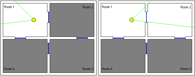
At the left, the camera does not look at any portal, so no room except for the one the camera is currently in is visible. At the right, the camera does look at the portal from room 1 to room 2, so room 2 is also visible. A last special case follows. The camera can not only see rooms that are behind visible portals, which lead from the current room to another room, but also rooms that are behind a visible portal that leads from any visible room to another room. Again here's a graphic to illustrate this.

As you can see room 1, room 2 and room 3 are visible. Room 1 is visible, because the camera is in this room, room 2 is visible because the portal from room 1 to room 2 is in the visible area of the camera and room 3 is visible, because a portal that neighbors a visible room and leads to room 3 is in the visible area of the camera. Something's going wrong here, though, because it's quite easy to see that room 3 is not actually visible. This is a little error that can easily occur with the portal engine of Ultimate 3D. But there's a way to avoid this problem in many cases. Usually doors close behind the character once he has passed through. If it's closed you can not see what's behind it anymore and this effect is being used by Ultimate 3D. In case a portal is set to closed, rooms that lie behind this portal will not be visible, even if the portal itself is in the visible area of the camera.
From all these examples you can see the utility of the portal engine very well. In a usual level in a bigger game there can easily be twenty rooms in a level. Rendering all of them in every frame would be total overkill for the CPU and the graphics device. Using the portal engine you can reduce the number of rooms that need to be rendered simultaneously to only one single room, which is quite an amazing performance gain. It gets even better, because using the portal engine takes no significant computing time at all. The only disadvantage is that it's quite a lot of work to specify all portals and to assign all objects (or at least most of them) to rooms. Different mechanisms, which could have assigned objects to rooms automatically, were considered during the development of Ultimate 3D 2.0, but most of them turned out to be not simple enough or not reliable enough. And seriously, how much work do you spend on your game? Seen in relation to the giant performance gain the bit of additional work is quite insignificant. Also, a level editor that is meant to be used with Ultimate 3D is being planned and it will make the use of the portal engine a lot easier. Anyway this project is nothing but a plan at the moment, so do not expect it anytime soon.
Well, that was a lot of theory, but if you understood all of it, the functions will be almost self-evident to you. The first function you need to know about enables the portal engine for a particular camera object.
This function enables the portal engine for the camera object it's being called by.
SwitchPortalEngine(
EnableDisable
) |
|---|
EnableDisable
Whether the portal engine is to be enabled (true) or disabled (false).
Once the portal engine is enabled any call to SetRoomVisibility(...) will be ignored. Anyway there is a good replacement for this. This function can be used to enforce the visibility of a room for the camera it is called by, even if the portal engine is enabled.
SetRoomVisibilityEnforcement(
RoomIndex,
NewVisibilityEnforcementState
) |
|---|
RoomIndex
The index of the room you want to set up the visibility enforcement state for. This can be an arbitrary integer value in the range from 0 to 1999.
NewVisibilityEnforcementState
The visibility enforcement state you want to set up for the given room. If this is true the room will be visible under all circumstances, otherwise the visibility depends on the portals (or on SetRoomVisibility(...) if the portal engine is disabled). For room 0 visibility enforcement is enabled by default, for all other rooms it is disabled by default.
The next four functions can be used to create, modify, close and destroy portals. As said above, portals are represented by circles. A circle is defined by an orientation (facing direction), a center and a radius. Additionally, the portal holds two room indices.
This function creates a portal using the given data and returns its identifier.
CreatePortal(
CenterX, CenterY, CenterZ,
FacingDirectionLongitude, FacingDirectionLatitude,
Radius,
RoomIndex1, RoomIndex2
) |
|---|
CenterX/Y/Z
The center of the circle which defines the portal.
FacingDirectionLongitude, FacingDirectionLatitude
The facing direction of the circle which defines the portal. If you build a ray from these two angles the circle will be orthogonal to this ray.
Radius
The radius of the circle which defines the portal.
RoomIndex1, RoomIndex2
The indices of the rooms that are at the different sides of the circle. These must not be 0, because the room with the index 0 is always visible when the portal engine is enabled and should not be seen as an actual room. The order of these parameters does not matter. If a camera is in the room with RoomIndex1 and moves through the portal it will be in the room with RoomIndex2 after that, and vice versa.
This function can be used to modify a portal after creating it.
SetPortal(
PortalID,
FacingDirectionLongitude, FacingDirectionLatitude, Radius, RoomIndex1, RoomIndex2
) |
|---|
PortalID
The identifier of the portal you want to modify. This is the return value of the call to CreatePortal(...) that created the portal.
FacingDirectionLongitude, FacingDirectionLatitude, Radius, RoomIndex1, RoomIndex2
See above.
This function can be used to open the portal (it's open by default) or to close it.
OpenPortal(
PortalID,
OpenClose
) |
|---|
PortalID
The identifier of the portal you want to modify. This is the return value of the call to CreatePortal(...) that created the portal.
OpenClose
Pass true to open this portal or false to close it. If a portal is closed the camera will still be able to pass through it to get to another room, because portals do not do any collision detection, but rooms that could be seen through the portal will not be visible anymore.
This function destroys the portal with the given identifier.
DestroyPortal(
PortalID
) |
|---|
PortalID
The identifier of the portal you want to destroy. This is the return value of the call to CreatePortal(...) that created the portal.
A piece of information which can not be found through the use of portals is which room the camera is in initially. For this reason you need to be able to set this up manually. This can be done through the function SetObjectRoom(...) just like for all other objects.
The portal engine does not just give you a performance increase, it can also be very helpful to code gameplay-related things. For example you can start a particular video sequence if the camera passes through a particular portal for the first time. It can also be useful for AI programming. If the camera is in the same room as the enemy, the enemy needs to get active. To realize things like this, you need to be able to find out which room an object is currently in. This information can be retrieved through the following function.
This function retrieves the index of the room the object calling it is currently in.
GetObjectRoom() |
|---|
Other than that you can avoid lots of unnecessary calculations by performing them only for objects which are in a visible room. For example particle systems do not need to be updated unless they can be seen by the camera, and objects do not need to check for collisions with objects in other rooms. To find out whether a room can be seen by a particular camera you can use the following function.
This function returns whether the room with the given index can be seen by the camera it's called by.
GetRoomVisibility(
RoomIndex
) |
|---|
RoomIndex
The index of the room of which you want to retrieve the visibility state.
Lots of advantages of the use of the advanced culling functions have already been mentioned. They increase the performance strongly, they can be used to avoid the unnecessary execution of code, they make the collision detection more efficient, they can be helpful for AI and they give you the possibility to control which light source effects which object. Here comes another advantage. The use of the advanced culling functions also gives you the possibility to have different ambient lighting for different objects. SetAmbient(...) specifies a particular ambient lighting color for all rooms. You can change this color for single rooms using the following function.
This function changes the ambient lighting color for a given room.
SetRoomAmbient(
RoomIndex,
AmbientColorR, AmbientColorG, AmbientColorB
) |
|---|
RoomIndex
The index of the room for which you want to specify a new ambient lighting color.
AmbientColorR, AmbientColorG, AmbientColorB
The ambient lighting color, which is to be set up for this room. For more information about ambient lighting refer to the description of SetAmbient(...).
Note that every call to SetAmbient(...) will overwrite the changes made by this function.
© Christoph Peters. Some rights reserved.