

In some cases it may happen that you have to modify the geometry of an object while the game is running; for example, if you have an object that can be deformed by hitting it with a particular weapon. This deformation could be realized using a vertex shader. But that's quite complicated. For this reason Ultimate 3D gives you the possibility to manipulate the geometry of a mesh in real time. You can edit every single vertex of the mesh. You can also modify the way the vertices get put together into triangles. And you can change the material that's being used for a triangle. You could actually use Ultimate 3D to make a modeling program, since it's possible to create meshes from nothing.
It is also quite common that the animation of a model has to be changed. For example, in 3rd person games you may want the torso or the head of the character to rotate when he looks in another direction. This can be done with Ultimate 3D in two different ways.
Before I explain how to manipulate mesh geometry, I'll give an explanation of the term mesh itself, since it may be that you do not have an exact idea of what it is. A mesh is a piece of geometry. It can be made up of an arbitrary number of vertices and triangles. If you have an *.md2 file, every frame is one mesh. If you have a *.3ds file, it may be that the model is made up of multiple meshes. If you have an animated *.an8 file, every object you created in Anim8or is one mesh. In addition, a copy of every single mesh will be created when you add a new LoD to a model.
It's very important to keep in mind that Ultimate 3D will never create the same mesh twice! If you load a model from a file, all objects that are based on this model will use the same meshes. It would be an unbelievable waste of memory if it wasn't done like this. So if you modify the mesh of one object, this mesh will be modified for every single object that's loaded from the same file. For other information, like materials and bones, this is not the case because these do not take much memory.
Now there's another new term you need to know about. So far you have learned that every 3D object is made up of vertices and that these vertices are put together into triangles. So every triangle is made up of three vertices. Now have a look at the following illustration.
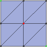
As you can see, this rectangle is made up of nine different vertices (marked by the little squares) and eight triangles. Since every triangle is made up of three vertices, you probably assumed that this little mesh requires 8*3=24 vertices to be described. But there are only nine different vertices, and only two of them are used by only one single triangle (marked green). The vertex in the middle is used by six triangles. And things like this happen really often. Fortunately, a simple method was invented a long time ago to avoid this waste of memory. If you have complex models, it may happen that the model has twice as many triangles as vertices. So how does it work? It's pretty simple. You save every vertex exactly once. The order does not matter. Then you add a so-called index buffer (and that's the term you need to remember) that contains three indices (integer numbers that refer to vertices) for every triangle. So actually a triangle is not made up of three vertices, but of three references to vertices.
After this bit of theory it's time for some practice. In Ultimate 3D you can lock any mesh of any model object at any time. Locking a mesh means preparing it for retrieving and changing its information. This is necessary because the memory the mesh data is saved to may be managed by the graphics device. It is very important that you unlock every mesh you lock. If you fail to do this, it may happen that an access violation occurs when the mesh gets rendered, and that can lead to miscellaneous rendering errors or one of Game Maker's "unexpected errors". To lock meshes there's the following function:
This function locks the given mesh of the object it's called by.
LockMesh(
LockedMeshIndex,
MeshIndex,
Frame,
LoD
) |
|---|
LockedMeshIndex
In Ultimate 3D you can not lock more than 32 meshes at the same time. It would have been no problem to set up a higher limit here, but if you do not forget about unlocking meshes you will never have more than 32 meshes locked at the same time anyway. The value for this parameter has to be in the range from 0 to 31. It's the index the locked mesh will be associated with.
MeshIndex
The index of the mesh you want to lock. I recommend writing a for-loop to loop through all meshes of the object. You can use the function GetMeshCount() to get the number of meshes an object has per frame.
Frame
The frame in which you want to modify a mesh. If you aren't using this function to lock a mesh of a model loaded from a *.md2 file, or of an object that has been created with AddFrame(...), you should always put 0 for this parameter.
LoD
The level of detail you want to modify. The highest level of detail has the index 0. This is also the value you should enter if you aren't using multiple levels of detail for the model.
This function unlocks a mesh and sets the information associated with the locked mesh index back to the defaults. It has to be called once for every call to LockMesh(...)!
UnlockMesh(
LockedMeshIndex
) |
|---|
LockedMeshIndex
The index of the mesh you want to unlock.
Once you've locked a mesh you can modify it in any imaginable way. You can modify its vertex data, its triangle index data and the materials that are associated with the single triangles. You can also reference all this information. For each of these tasks there's a different function:
This function modifies a single vertex of the locked mesh with the given index:
SetLockedMeshVertex(
LockedMeshIndex,
VertexIndex,
ValueIndex,
NewValue
) |
|---|
LockedMeshIndex
The index of the locked mesh you want to modify. This is the value you put as the first parameter when calling LockMesh(...) to lock the mesh.
VertexIndex
The index of the vertex you want to modify. I recommend writing a for-loop to cycle through all the vertices. You can use GetLockedMeshVertexCount(LockedMeshIndex) to get the number of vertices the given locked mesh has.
ValueIndex
This parameter gives the part of the vertex information that is to be changed. Since Ultimate 3D uses a different coordinate system than Game Maker, this information is sorted in the following way:
0 = VertexPositionX
1 = VertexPositionZ
2 = VertexPositionY
3 = VertexNormalX
4 = VertexNormalZ
5 = VertexNormalY
6 = VertexTextureCoordinate1U
7 = VertexTextureCoordinate1V
Then the texture coordinates that have been added using AddTextureCoordinateSet(...) follow. The vertex normal is a vector needed to calculate the lighting of objects. Usually there's no need to modify it manually. If you change the geometry of the mesh, you should call RecalculateNormals() once to update the normals.
NewValue
The new value you want to set up for the given part of the given vertex.
This function returns a part of the information of a single vertex of the given mesh:
GetLockedMeshVertex(
LockedMeshIndex,
VertexIndex,
ValueIndex
) |
|---|
LockedMeshIndex
The index of the locked mesh you want to modify. This is the value you put as the first parameter when calling LockMesh(...) to lock the mesh.
VertexIndex
The index of the vertex you want to modify. I recommend writing a for-loop to cycle through all the vertices. You can use GetLockedMeshVertexCount(LockedMeshIndex) to get the number of vertices the given locked mesh has.
ValueIndex
This parameter is exactly the same as ValueIndex in SetLockedMeshVertex(...), so have a look at the description there.
This function changes the vertices that are being used for the triangle with the given index of the given locked mesh.
SetLockedMeshTriangle(
LockedMeshIndex,
TriangleIndex,
VertexIndexA, VertexIndexB, VertexIndexC
) |
|---|
LockedMeshIndex
The index of the locked mesh you want to modify. This is the value you put as the first parameter when calling LockMesh(...) to lock the mesh.
TriangleIndex
The index of the triangle you want to change. I recommend writing a for-loop to cycle through all the triangles. You can use the function GetLockedMeshTriangleCount(LockedMeshIndex) to get the triangle count of the given locked mesh.
VertexIndexA, VertexIndexB, VertexIndexC
The indices of the vertices that are to be used for the triangle. Note that the order of these parameters do matter, due to the back face culling. You must never enter a value bigger than the vertex count of the given locked mesh here. This could lead to serious display problems.
This function retrieves a single vertex index of a triangle in the given locked mesh:
GetLockedMeshTriangle(
LockedMeshIndex,
TriangleIndex,
RequestedVertexIndex
) |
|---|
LockedMeshIndex
The index of the locked mesh you want to retrieve information from. This is the value you entered for the first parameter of the LockMesh(...) function when locking the mesh.
TriangleIndex
The index of the triangle you want to retrieve information about. I recommend writing a for-loop to cycle through all the triangles. You can use the function GetLockedMeshTriangleCount(LockedMeshIndex) to get the triangle count of the given locked mesh.
RequestedVertexIndex
For this parameter you can pass 0, 1 or 2 to retrieve the first, second or third vertex index of the triangle.
This function changes the material that is used for the given triangle of the given mesh:
SetLockedMeshTriangleMaterial(
LockedMeshIndex,
TriangleIndex,
NewMaterialIndex
) |
|---|
LockedMeshIndex
The index of the locked mesh you want to change the triangle's material for. This is the value entered for the first parameter of the LockMesh(...) function when locking the mesh.
TriangleIndex
The index of the triangle whose material you want to change. I recommend writing a for-loop to cycle through all the triangles. You can use the function GetLockedMeshTriangleCount(LockedMeshIndex) to get the triangle count of the given locked mesh.
NewMaterialIndex
The new index of the material you want to set up for the triangle. You can use GetMaterialIndex(...) to get this value.
This function returns the index of the material that's currently being used by the given triangle of the given locked mesh.
GetLockedMeshTriangleMaterial(
LockedMeshIndex,
TriangleIndex
) |
|---|
LockedMeshIndex
The index of the locked mesh you want to retrieve information from. This is the value you put for the first parameter of the LockMesh(...) function when locking the mesh.
TriangleIndex
The index of the triangle you want to get information about. I recommend writing a for-loop to cycle through all the triangles. You can use the function GetLockedMeshTriangleCount(LockedMeshIndex) to get the triangle count of the given locked mesh.
There is another model manipulation function which has been mentioned a couple of times before. It can be used to add a new set of texture coordinates to all meshes of an object (the meshes mustn't be locked when doing this). You have already seen how to fill the added texture coordinates with data using the function SetLockedMeshVertex(...). One easy way to get the data is creating two versions of the same model with two different sets of texture coordinates. Then you can create a temporary instance of the second version of the model, lock its meshes and the meshes of the first model, and copy the texture coordinates of the second model to the first model in a few for-loops. When you are done with this you can destroy the temporary second model. But let's get to the function.
This function can be used to add a new multi-dimensional texture coordinate set to all meshes of the object that calls the function (and all objects that are based on the same model!).
AddTextureCoordinateSet(
DimensionCount
) |
|---|
DimensionCount
The number of dimensions the texture coordinate set should have. This value can be an integer value in the range from 1 to 4. One dimension means that there's only one real value in the texture coordinate (U), two dimensions mean that there are two (U, V), three dimensions means that there are three (U, V, W) and four means that there are four (U, V, W, Q).
Finally there's a function that makes the use of multiple texture coordinate sets a lot easier. Often you simply need to load two different texture coordinate sets for one model. For example light mapping requires one texture coordinate set for the diffuse maps and a second texture coordinate set for the light map. The problem is that none of the supported model file formats except *.u3d support multiple texture coordinate sets. The solution to this problem is creating two versions of the model, each of them having a different texture coordinate set. Then you can use the following function to combine both of them.
This function copies all texture coordinate sets of the given model to the meshes of the model object that calls this function and to all objects that are based on the same model file. The meshes of this object mustn't be locked.
AddTextureCoordinateSetsFromModel(
ModelFile, Password
) |
|---|
ModelFile
The model file that holds the texture coordinate sets that are to be added. This model file must have the same number of meshes as the model object calling this function, and all meshes must have the same number of vertices.
Password
If ModelFile refers to an encrypted Ultimate 3D model file, you can pass the correct password for this parameter. Otherwise you have to pass nothing or an empty string.
Especially in third person games it happens very often that the character needs to move interactively. For example if you've got a character with a weapon aiming somewhere, his torso has to rotate up and down while the player aims up and down, to make it look realistic. Ultimate 3D offers two different ways to do this. The first one simply changes the rotation of a particular bone. This can be used to reach the desired effect quite easily, but it does not necessarily look that good. For this reason there's also the possibility to make particular bones use other frame values than other bones. This way you can for example make the upper part of the body of a character use a different animation than the rest. For both methods you need a function to retrieve the index of the bone you want to modify.
This function returns the index of the bone with the given name, or 0 if it does not exist.
GetBoneIndex(
BoneName
) |
|---|
BoneName
The name of the bone. What this is depends on the modeling program you are using.
If you want to do something automatically for all bones in a model it is useful to write a loop, which cycles through all bones in a model. For this purpose you need to know how many bones are part of the model. This information can be retrieved through the function GetBoneCount() which returns the number of bones available in the model object it is called by. All integer values in the range from 0 to GetBoneCount()-1 are valid bone indices. Another function, which is useful when you want to have code that works with bones automatically is the following.
This function returns the index of the parent bone of the bone with the given index. If the bone does not have a parent bone -1 is returned.
GetBoneParent(
BoneIndex
) |
|---|
BoneIndex
The index of the bone for which you want to retrieve the index of the parent.
The next function is the one which can be used to rotate a single bone. It usually looks quite unrealistic when it is used for character models, but it can be very useful for mechanical objects like tanks. For example it is very easy to make the turret of a tank rotate with this function.
This function deletes all rotation keys of the bone with the given index of the object that calls the function and creates one single new rotation key with the given rotation.
SetBoneRotation(
BoneIndex,
RotationX, RotationY, RotationZ
) |
|---|
BoneIndex
The index of the bone you want to change.
RotationX, RotationY, RotationZ
The new rotation. The variables get interpreted in the same way as the variables rotx, roty and rotz of model objects.
Here is the last function, which can be used for really authentic interactive character animations. For example you could make a model that has an animation for the upper part of the body in which it aims up and down and different running animations for the legs. Then this function could be used to make the upper part of the body aim up and down depending on the place the player aims at, while the legs are running into different directions or standing.
This function can be used to set up another frame value for a particular bone of the object it is called by.
SetBoneFrame(
BoneIndex,
Frame,
AffectChildBones |
|---|
BoneIndex
The index of the bone you want to change the frame value for.
Frame
A positive value giving an absolute frame value, which is to be used for the bone. It will be used instead of the value of the frame variable, resp. the return value of GetCurrentFrame().
AffectChildBones
If you pass true for this parameter, the given frame value will be used not only for the bone with the index BoneIndex, but also for all bones that are attached to this bone. Otherwise only this bone will be affected. If one of the child bones has its own individual frame value set up through SetBoneFrame(...) this one will be used instead, no matter whether you pass true or false.
Another important type of animation manipulation is the interpolation between two poses within an animation. Imagine your character is currently running. Then the player stops pressing the key that makes him run, so the character has to hold. Now it would be quite ugly if the animation would just jump back to the idle animation. It would be nicer if it would interpolate from the running animation to the idle animation smoothly. This is what the interpolation of poses is good for.
This function starts an interpolation from the current pose to the pose the model has at the given destination frame.
StartPoseInterpolation(
DestinationFrame,
InterpolationDuration
) |
|---|
DestinationFrame
The frame at which the model has the destination pose.
InterpolationDuration
The time the interpolation will take in steps. Over this time interval the object will be interpolating between the poses. After that it will continue playing the animation at DestinationFrame unless the values of first_frame and last_frame do not allow this. If you want to abort the interpolation of a pose you can call this function again and pass zero for this parameter.
When you have a model with very many different animations you may find it uncomfortable to have all these animations in one file, with one animation sequence after the other. It would be nicer to have one file for every animation. Ultimate 3D offers a feature for this purpose. It is not a perfect solution, but it works. It allows you to load animations from model files.
This function copies an animation from a given model file to the model object it is called by. It does this by replacing all keyframes in the animation of this model object, by those saved in the given model file.
CopyAnimation(
SourceFile,
SourceFilePassword,
CopyRotationKeysOnly
) |
|---|
SourceFile
The source file from which you want to copy the animation. You may want to preload this model file through PreloadMesh(...) to avoid a delay.
SourceFilePassword
If the source file is an encrypted Ultimate 3D model file (*.u3d) you can pass the password to this parameter. Otherwise you should pass an empty string.
CopyRotationKeysOnly
If this parameter is true the function will copy exceptionally rotation keys, otherwise all keys well be copied. If the skeleton of the destination model object does not match the skeleton of the source model exactly this may be desirable.
This function should be used carefully. It can only work correctly if the source model and the destination model object have identical skeletons. If you pass true for CopyRotationKeysOnly it may also work for models, with slightly different skeletons, but you should not rely on this.
In some cases it's necessary to create meshes from scratch. This can easily be done with Ultimate 3D. You create these objects in the same way as all other objects. First you set up a few variables, then you call a creation function once, and finally you have to add Step() and Destroy() to the corresponding events.
material_count
The number of materials the new object will have. This value cannot be zero.
vertex_count
The number of vertices the only mesh of the new object will have. It must be bigger than three.
triangle_count
The number of triangles the only mesh of the new object will have. This value cannot be zero.
After setting up these variables you can call CreateEmptyMesh(). Then an object with the given material, vertex and triangle count will be created and associated with the object that called the function. After you have added Step() and Destroy() the object is ready to be used. But before you get some visible results you have to use the model manipulation functions I introduced above to fill the mesh with valid geometry. By default all vertex data and index data will be filled with zeros and all materials will be white and untextured.
There is a couple of mesh manipulation operations which need to be done very often. Ultimate 3D offers a few easy-to-use functions to perform these operations. The most important one recalculates the normal vectors that are required to get correct per vertex lighting. Another one smoothes the normals of the meshes. This means that it searches for vertices that have the same position but a different normal to fix this. The third one calculates something called inverse tangent space matrices for every single vertex. A brief explanation of what this means can be found below.
This function calculates a vertex normal for every vertex of every mesh of the object that has called the function. It should be called whenever you change the mesh geometry, because then the old normals will not be current anymore. It does not take any arguments.
RecalculateNormals() |
|---|
It happens quite often that visible creases occur in the surface if the normals are calculate this way. Since normals are not only required for light calculations but also for effects such as cel-shading and environment mapping this is very undesirable. The following illustration shows a model, which uses environment mapping, looks if there are creases in it.

To avoid this, Ultimate 3D offers a simple function. It searches for creases in the model and if it finds some it smoothes them. Here is its description.
This function searches for vertices with identical positions, but different normals. If it finds some it checks whether the angle between their normals is smaller than the given angle and if so it smoothes them. Note that this process is very computing time intensive.
SmoothNormals(
SmoothingAngle
) |
|---|
SmoothingAngle
The smoothing angle in degrees. The function smoothes the normals of two vertices only, if the angle between them is smaller than this angle.
The next function has a very special purpose. Unless you want to get into pixel shader programming you do not need to undestand it. You may want to skip the following explanation. Lots of special effects, especially those, which implement some sort of per pixel lighting, use normal maps. Normal maps give normals in the space of the texture. This space is called tangent space. Information like the position of light sources usually is given in the space of the mesh. For this reason a way is needed to get the information about the light source from mesh space into tangent space. A matrix (see the chapter about math functions) is needed that brings information from mesh space into tangent space. And since every triangle is textured differently this matrix is needed for every vertex.
This function calculates inverse tangent space matrices (mesh to tangent space) for each vertex of each mesh of the object that calls the function, meaning that it overwrites the mesh normals with the third column of the matrix. Usually the third colum is very similar to the normals, so this is no big change. It also adds two new 3D texture coordinate sets. The first one of them will be used to save the first column of the inverse tangent space matrices, the second one will be used to save the second column. The function does not take any parameters.
AddInverseTangentSpaceMatrices() |
|---|
Cel-shading is a technique that's commonly used to create graphics that look as if they are part of a comic. It can also be used to mark particular objects by creating an outline around them. Cel-shading basically creates an extruded version of each mesh and renders it using reverse back face culling. This results in an outline around the model. When applying cel-shading you can define the width of the outline in mesh space and the color of the outline. Commonly the color of the outline is solid black. But you can also use other colors to achieve other pretty cool effects. For example you can use a transparent red to get a strong accent for the object the effect is applied to. Enabling cel-shading is pretty easy. Here's the function that does it:
This function enables cel-shading for the model object it's called by.
ApplyCelShading(
LineWidth,
LineColorR, LineColorG, LineColorB, LineColorA
) |
|---|
LineWidth
The width of the outline you want to create in mesh space.
LineColorR, LineColorG, LineColorB, LineColorA
The color of the outline. The values for these parameters should be between 0 to 255. LineColorA gives the opacity of the outline. 0 means no opacity (fully transparent) and 255 means fully opaque.
Note that cel-shading uses a vertex shader. For this reason models that use vertex skinning and cel-shading mustn't use more than 28 bones, otherwise some bones will not get applied correctly.
© Christoph Peters. Some rights reserved.